| |
| YSMA18 - Bargraph replacement |
- Remove the top cover and the front panel
- Remove the old TFK bargraph
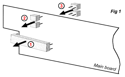
- Remove the 330nF mylar capacitors, and solder them on the back side of the main board (fig #1).

- Install the new bargraph (Steadily apply it to the main pcb to avoid mechanical problems - fig #2)

- Test: the bargraph should indicate approximately 0dB when a +6dBm/1KHz sinusoidal signal is present to the output and the output level is calibrated at +6dB.
|
|
 |