| |
|
Controls

|
| Right side |
 |
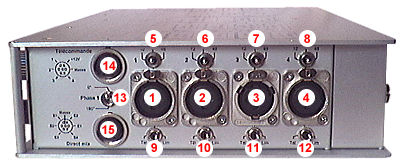
| 1 to 4 |
Mic/Line inputs |
| 5 to 8 |
12v/48v phantom mic power switches |
| 9 to 12 |
Remote/limiter switches |
| 13 |
Phase/track 1 |
| 14 |
Remote control socket |
| 15 |
"Mixer" in/out socket |
|
| Left side |
 |
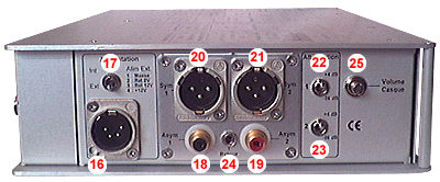
| 16 |
+12 v dc power supply input/output socket |
| 17 |
Batt / External power switch |
| 18 + 19 |
Asymmetrical outputs (-2dBm or -12dBm) |
| 20 + 21 |
Symmetrical outputs (+4dBm or -56dBm) |
| 22 + 23 |
Symmetrical output level switch |
| 24 |
Tape return input |
| 25 |
Headphone level potentiometer |
|
| Front panel |
 |
| 26 |
On/Off switch |
| 27 |
Headphone output |
| 28 |
Batt test/reference switch |
| 29 |
Direct/tape return monitoring switch |
| 30 |
Monitoring selector (mono/stereo/MS) |
| 31 + 32 |
Vu-meters/modulometers (depending on the version) |
| 33 to 36 |
Input level setting potentiometers |
| 37 to 40 |
Input trims (12 x 6 dB step) |
| 41 to 44 |
Pan potentiometers |
| 45 to 47 |
Low-cut filters (80Hz - 160Hz) |
| 48 |
Tracks 1 2 - stereo link |
| 49 |
Peak/limiters indicators |
|
|
|
Power Supply

|
The mixer operates on 8 batteries (C size) as well as an external power supply unit through socket #6 (XLR 4).
Operation on batteries:

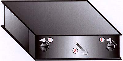
To insert new batteries, open the rear hood (use a coin to unscrew both locks).
Pull the hood to the rear; batteries must be placed as shown.

We do recommend using only new alkalines batteries. The use of NiCd or NiMh accumulators would reduce the autonomy by 50%. Old batteries could leak, damaging your mixer. Please remove old batteries from your mixer if
you are not planning to use it for a long period.
Close the hood .
Set the switch #17 to “Int”.
Switch the mixer on: Switch #26 to “On”
The batt level can be displayed by the Vu-meter #31: Switch #28 to “Batt”.
With new batteries, it will show approximately “12v”. Batteries have to be replaced when the battery level goes under “6v” and a red light appears behind the vu-meter. Below this limit, the mixer may
not operate properly.
External power supply:
The external supply socket allows to connect both an external supply source and external devices such as HF transmitters. Switching the mixer off will switch the connected external devices off as well.
Pinout:
- 1: External supply ground
- 2: Accessories ground output
- 3: Accessories +12 volts cc output
- 4: External +12 volts cc input
Switch #17 to “Ext”.
Actually, the mixer can operate with any CC supply source between 6 to 15v, which makes it easy to use with various existing accumulators or power units (such as the "Sony-Betacam" ones).
In case the mixer and another piece of equipment are both supplied from the same external power source, never connect the battery ground to the chassis ground nor the signal ground - especially the audio input/output
connectors. The audio signal would suffer interference, and the internal supply unit could get damaged.
|
|
Connections

|
Inputs:
All the input connectors (except the external power supply and the tape return sockets) are located on the right side of the mixer.
Mic/Line inputs:
The XLR 3 pin sockets #1 to 4 can support any kind of microphone - dynamic, static 12/48 Phantom - or a line level signal.
Pinout:
Depending on the signal and the microphone, input level will be adjusted with the input trims #37 to 40. (12 x 6 dB step - from 0 dBm to -70 dBm)
Microphones will be powered accordingly to the switches #5 to 8.
- Central position: no power
- Position “12”: 12v phantom power
- Position “48”: 48v phantom power
The input #1 is fitted with a phase inverter ( switch #13 )
- Position “0°”: Normal phase
- Position “180°”: Inverted phase
Remote input:
One can connect a remote unit to the "Din" socket #14.
Pinout:
- 1: Remote control track #1
- 2: Remote control track #2
- 3: Remote control track #3
- 4: Remote control track #4
- 5: Gnd
- 6: +12v out
- 7: NC
Tape back:
In order to monitor the recorded signal, connect the output line of your recorder to the "minijack" socket #24:
Depending on recorders, the tape return might have to be adapted for comfortable use. If you can notice a difference between the direct/return signals, please contact your dealer for a setting.
To commute the direct/back monitoring, use the switch #29:
- “Dir”: Monitoring of the output signal
- “Ret”: Monitoring of the tape return (socket #24)
Outputs:
All the outputs (except the "mixer" one) are located on the left side of the mixer.
Line outputs
Two different types of outputs are available at the same time:
Asymmetrical outputs to the “Cinch” sockets #18 and 19
Symmetrical outputs to the “XLR” sockets #20 and 21
Note: Some mixers are fitted with a Hirose ten-way or an XLR 7 connector output panel. In such a case, check the specific pinout.
The asymmetrical output level can be adjusted to -2 dBm or -12 dBm. The factory setting is -12dBm.
The asymmetrical output level can be set at +4dBm or -56dBm, with the switches #22 and 23.
Note: Do not connect a 48v-phantom powered mic. input to the symmetrical output.
XLR sockets pinout:
"Mixer"
The "Din" socket #15 allows to connect any multi-track external equipment.
Pinout:
- 1: Output track #1
- 2: Output track #2
- 3: Output track #3
- 4: Output track #4
- 5: Input mix #1 / right - max input level: +15 dBm
- 6: Input mix #2 / left - max input level: +15 dBm
- 7: Gnd
|
|
Advanced use

|
Preamplifier setting:
Sensitivity and Gain:
Depending on the signal and the microphone, the input level will be set with the input trims ( #37 to 40 )
(12 x 6 dB step - from 0 dBm to -70 dBm)
For example:
- Line level signal -> Input sensitivity at 0dB
- Static microphone -> Input sensitivity from -34 to -52 dB
- Dynamic microphone -> Input sensitivity from -58 to -70dB.
The recording level will be precisely adjusted with the gain potentiometers #33 to 36.
Warning: In case the sensitivity gets too hight the output signal could get distorted, even if you lower the gain control. The input stage amplifier could get saturated.
Limiter:
Switches #9 to 13.
Pan pots:
On each track, the signal can be assigned to both outputs, with the potentiometers #41 to 44:
- Position “1”: to output #1 (Left) only
- Position “2”: to output #2 (right) only
- Other: to both tracks (ratio depends on the position)
Filters:
Switches #45, #46 and #47:
Stereo operation:
The switch #48 allows to link the commands of both tracks #1 and 2:
- Position "2 tracks": separate commands
- Position “Stereo”: linked commands to track #1
Headphone monitoring:
Headphone is plugged to socket #27.
Impedance must be greater than 32 ohms.
To commute the direct/back monitoring, use the switch #29:
- “Dir”: monitoring of the output signal
- “Ret”: monitoring of the tape return (socket #24)
Rotating switch #30 operates as follows:
- Position ”Mono”: Mono monitoring (Sum of outputs #1 and 2)
- Position “1”: Mono monitoring track #1
- Position “2”: Mono monitoring track #2
- Position “Stereo”: Stereo monitoring (Track #1: Left, Track #2: Right)
- Position “M/S”: Stereo monitoring (M/S decoding)
The monitoring level is set with the potentiometer #25.
Battery test and reference:
Switch #28 allows the batteries to be tested and to send a reference tone as well:
- Central position: Nothing
- Position “Batt”: Battery test
- Position “Ref”: Tone reference to the outputs
Note: With most mixers, the tone reference sends 2 different tones: 1000 Hz to the left, 2000 Hz to the right. But on request, it will send only a 1000 Hz tone on both tracks.
The batt level is displayed on the vu-meter #31
With new batteries, it will show approximately “12v”. Batteries have to be replaced when the battery level goes under “6v” and a red light appears behind the vu-meter. Below this limit, the mixer
may not operate properly.
Note: when tone is sent to the outputs, the audio signal is switched off.
Peak / Limiters indicators:
Operate as follows:
- Off: Limiter off/output level < +20 dBm
- Green: Limiter on but inactive
- Orange: Limiter on and operating
- Red: Limiter off/output level > +20 dBm
|
| [Back] |
|
|
 |